In ConcreteSection, the Stress Results for each result case are determined using equilibrium, strain compatibility, and the constitutive models for both concrete and steel as discussed in the Analysis section of the help file. Note: The Stress Results view is inactive when no loads are applied to the reinforced concrete section.
The Stress Results view graphically shows the results on the cross-section for the result case selected in the tab. This view shows the cracked neutral axis of the section and the compressive stress or strain in the concrete. Additionally, the force, stress, or strain can be viewed for each bar of reinforcement in the cross-section. Use the to set which results are displayed graphically for the concrete and reinforcement. Color contour legends are available so that the range of values displayed can be controlled.
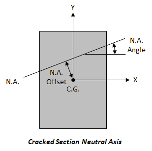
The tab displays several sets of results in the Case Summary including: the applied axial load and bending moment for the result case; concrete ultimate stress and strains; reinforcement force, stress and strain ranges; cracked section properties; interaction diagram extreme points; and uncracked-transformed section properties. The uncracked geometric properties, such as A, Ix, Iy, Sx, Sy, are calculated using an uncracked section with the steel transformed to an equivalent concrete area. This is done using the modular ratio. The cracked neutral axis offset and angle of rotation are also reported and these values are measured with respect to the centroid and the x-axis respectively, as shown in the figure below.

Select the concrete or reinforcement bar(s) to view the numerical results in the tab for the selected Result Case.